
Choosing Industrial Aluminum Heat Sinks is a thermal design decision, not merely a purchasing task. The wrong profile can create hot spots, fan noise, and premature component failure. Avram Bar-Cohen, a recognized thermal management researcher, has emphasized, “Thermal design must be treated as a system problem, not an afterthought.” That principle remains practical on factory floors.
A reliable selection begins with the heat load, allowable case temperature, and available airflow. Check the heat sink’s thermal resistance under actual operating conditions. Catalog ratings often assume ideal orientation and clean air. Real equipment may face dust, vibration, restricted vents, or changing fan speeds. Aluminum alloys also matter. Extruded 6063 aluminum commonly offers balanced conductivity, machinability, and corrosion resistance. Higher fin density may improve performance, but only when airflow can pass through the channels. More fins are not always better.
Mounting deserves equal attention. Uneven pressure can leave microscopic gaps between the base and device. A suitable thermal interface material can reduce that resistance. Confirm its thickness, compression range, and long-term stability. Then test the assembly inside its enclosure. Measure temperatures at the device case, heat sink base, and fin outlet. Short tests can mislead.
The choice is rarely perfect.
Engineers should compare measured results with supplier data and document every assumption. Weight, cost, surface treatment, electrical isolation, and service access may change the final decision. This guide explains how to evaluate Industrial Aluminum Heat Sinks with practical criteria, while acknowledging one uncomfortable truth: a technically efficient design can still fail when installation conditions are ignored.
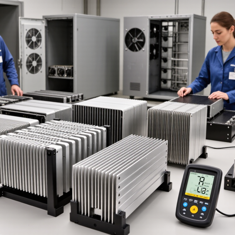
How to Choose Industrial Aluminum Heat Sinks?
Industrial aluminum heat sinks are passive thermal devices. They move heat away from electronic components. Their fins increase surface area, while air carries heat into the surrounding environment. A flat base contacts the hot component. Heat then travels through the aluminum and spreads across the fin structure.
The Aluminum Association’s Aluminum Standards and Data reports aluminum density near 2.70 g/cm³. This makes aluminum much lighter than copper for large enclosures. Common 6063 aluminum alloys provide thermal conductivity around 200 W/m·K. However, conductivity alone does not guarantee cooling. Fin spacing, airflow, surface orientation, and contact resistance also matter. JEDEC thermal-testing standards, including JESD51 methods, emphasize controlled conditions for comparing thermal resistance. Real factory airflow is rarely so controlled.
Tips: Match the heat sink’s rated thermal resistance to the component’s actual power. Check the calculation at the highest ambient temperature. Forced air can improve performance, but blocked fins can make it worse. A 3°C/W design may appear sufficient, yet poor mounting can add several degrees. Use a thin thermal interface layer and even fastening pressure. Measure the assembled unit with a thermocouple or infrared camera. Be careful with infrared readings on shiny aluminum; emissivity errors are common. A catalog value is useful, but field testing remains necessary.
Industrial aluminum heat sinks transfer heat away from electronic components through a conductive base and extended fins. The chart compares typical room-temperature thermal conductivity values for commonly used aluminum grades. Higher conductivity can improve heat spreading, while fin geometry, airflow, surface area, installation, and thermal interface quality also strongly affect the final cooling performance.
Choosing an industrial aluminum heat sink starts with thermal resistance, not appearance. Measure the device’s heat load, ambient temperature, airflow, and allowable junction temperature. JEDEC JESD51 testing methods emphasize defined boundary conditions, because published thermal values can change significantly in real assemblies. A sink rated at 5°C/W may perform poorly inside a dusty cabinet with restricted airflow.
Aluminum commonly offers thermal conductivity near 205 W/m·K, according to ASM materials data, while remaining lighter and easier to extrude than copper. Fin spacing must match the airflow pattern. Tight fins increase surface area, but they also raise pressure drop. Natural convection usually needs wider channels and taller fins. Forced airflow permits denser profiles, although fan failure becomes a practical risk.
Watch the operating environment. ASHRAE’s Thermal Guidelines identify 18–27°C as a common recommended inlet range for many air-cooled information-technology systems, but industrial enclosures may exceed it. The International Energy Agency reported that data centers consumed about 460 TWh globally in 2022, showing why efficient heat removal matters beyond laboratory testing. In field installations, I check mounting flatness, interface material thickness, vibration, corrosion, and dust buildup. A larger heat sink is not automatically better. Sometimes, the calculation is too optimistic. Test the complete assembly under peak load, then inspect the hottest component with calibrated measurement equipment.
| Selection Factor | Typical Data or Range | Why It Matters | Recommended Selection Guidance | Priority |
|---|---|---|---|---|
| Aluminum Alloy | 1050/1070: approximately 220–235 W/m·K 6063: approximately 200–210 W/m·K 6061: approximately 165–175 W/m·K Die-cast aluminum: approximately 90–120 W/m·K |
Thermal conductivity determines how efficiently heat spreads from the heat source into the fins. | Use high-conductivity wrought aluminum for maximum heat spreading. Select 6063 when extrusion performance and surface finish are important. | Very High |
| Thermal Resistance | Common industrial heat sinks: approximately 0.2–5.0 °C/W, depending on size, airflow, and mounting conditions. | Lower thermal resistance means a smaller temperature rise for the same heat load. | Compare thermal-resistance values using the same airflow, orientation, mounting interface, and test method. | Very High |
| Heat Load | Typical industrial applications range from less than 10 W to several hundred watts per component or assembly. | The heat sink must dissipate the maximum continuous power without exceeding the component temperature limit. | Size the heat sink using maximum heat generation, not average operating power. Include transient and worst-case conditions where applicable. | Very High |
| Available Airflow | Natural convection: approximately 0.5–2 m/s equivalent airflow Forced airflow: commonly 2–10 m/s |
Air velocity strongly affects convection and can reduce thermal resistance compared with still-air operation. | For fan-cooled designs, verify fan flow rate, pressure capability, noise, dust loading, and airflow direction. | Very High |
| Fin Geometry | Fin spacing commonly ranges from approximately 3–15 mm. Fin height is often approximately 10–100 mm, depending on the design. | Fin spacing and height control surface area, airflow resistance, and natural-convection performance. | Use wider fin spacing for natural convection or dusty environments. Use denser fins when clean, forced airflow is available. | High |
| Mounting Interface | Thermal interface materials may have thermal conductivity from approximately 1–12 W/m·K, depending on material type and thickness. | Contact resistance can significantly increase total thermal resistance when surfaces are uneven or clamping pressure is insufficient. | Use a flat base, suitable thermal interface material, controlled mounting pressure, and adequate contact area. | Very High |
| Operating Temperature | Aluminum heat sinks are commonly used across industrial ambient conditions from approximately −40°C to 85°C; the assembly limit depends on the alloy, coating, interface, and electronics. | Material properties, interface performance, and component reliability change with temperature. | Design for the highest ambient temperature and verify the component junction-temperature limit with a safety margin. | Very High |
| Manufacturing Method | Extrusion: suitable for long, continuous profiles Die casting: suitable for complex integrated shapes Machining: suitable for precision features and low-volume customization |
The manufacturing process affects fin geometry, dimensional tolerance, production volume, and cost. | Choose extrusion for standard fin profiles, die casting for integrated housings, and machining for precise or prototype designs. | High |
| Surface Treatment | Common options include anodizing, chemical conversion coating, powder coating, and bare aluminum finishing. | Finishing can improve corrosion resistance, electrical isolation, appearance, and durability, but may add thermal interface considerations. | Use anodizing or conversion coating for corrosion protection. Confirm coating thickness and emissivity requirements for natural-convection designs. | Medium |
| Weight and Size | Aluminum density is approximately 2.7 g/cm³, making it significantly lighter than copper at approximately 8.96 g/cm³. | Lower mass simplifies installation, reduces mechanical loading, and supports compact industrial equipment designs. | Check enclosure space, mounting strength, center of gravity, transport limits, and required clearance around the fins. | High |
| Corrosion Environment | Indoor industrial environments are generally less demanding than outdoor, marine, salt-spray, or chemically exposed environments. | Corrosion can reduce mechanical strength, degrade electrical contacts, and obstruct airflow through fin channels. | Specify protective finishing and compatible fasteners for humidity, salt, chemicals, and galvanic-corrosion risks. | High |
| Reliability and Safety Margin | A design margin of approximately 10–25% above the calculated thermal requirement is commonly used, subject to application standards and validation results. | A margin helps accommodate production variation, blocked airflow, aging, dust, and unexpected operating conditions. | Validate the complete assembly through thermal testing under worst-case ambient, load, orientation, and airflow conditions. | Very High |
Note: Values are typical engineering ranges for preliminary selection. Final heat-sink performance should be confirmed using the actual heat load, mounting interface, enclosure, airflow, ambient temperature, and applicable testing requirements.
Choosing an industrial aluminum heat sink starts with the application, not the catalog shape. Estimate the device’s real heat load, ambient temperature, airflow, and allowable case temperature. A control cabinet near a furnace needs a different design from an outdoor inverter exposed to dust.
ASM Handbook, Volume 2, lists aluminum 6063 thermal conductivity near 200 W/m·K at room temperature. That value helps, but it does not guarantee performance. Surface finish, mounting pressure, interface material, and airflow can reduce actual heat transfer. ASHRAE Handbook—Fundamentals reports natural-convection coefficients commonly around 2–10 W/m²·K, while forced airflow can raise them substantially. Design accordingly.
For sealed cabinets, use taller fins with generous spacing. Narrow channels may trap warm air. In dusty plants, oversized gaps are often easier to clean. For fan-cooled equipment, fin direction should follow the airflow path, not merely the extrusion direction. JEDEC JESD51 thermal-test methods also show why measured thermal resistance depends strongly on test conditions and mounting details.
Check the complete thermal path: component, interface pad, heat sink, and surrounding air. A simple calculation is useful. It is not the whole truth. Vibration may loosen fasteners, and corrosion may change contact quality over time. Include a safety margin of roughly 20–30% when load and airflow are uncertain. That margin may still be insufficient in high-temperature environments. Test a production-like assembly under peak load, blocked airflow, and realistic dust conditions.
Choosing an industrial aluminum heat sink starts with heat load, airflow, space, and production volume. The ASM Handbook reports thermal conductivity near 200 W/m·K for common 6063 aluminum alloys. That value is useful, but it does not guarantee low temperatures. Interface resistance, oxidation, mounting pressure, and airflow can dominate the result. Measure the assembly, not only the metal.
Extruded heat sinks suit repeatable designs with moderate thermal loads and predictable tooling costs. Their straight fins work well with forced airflow. Skived heat sinks create thinner, taller fins from a solid block. They can increase surface area where space is limited, but machining time and material waste usually rise. Stamped heat sinks use formed sheet metal. They are lightweight and economical for high-volume electronics, although their thermal mass and fin height are limited. They may disappoint under sustained loads. Custom heat sinks combine methods, cutouts, heat pipes, or unusual mounting features. They offer flexibility, yet poor tolerances can make installation inconsistent.
The U.S. Department of Energy has reported that cooling may consume about 40% of data-center electricity. This shows why airflow deserves equal attention. In practice, I would prototype two geometries and record temperature at identical power. Small mistakes happen. A cheaper stamped design may outperform a larger extrusion with blocked airflow. Thermal simulation helps, but testing remains necessary. Check corrosion, vibration, noise, and cleaning access before approving production.
Material selection should match the heat load, airflow, and operating environment. High-conductivity aluminum alloys transfer heat efficiently. However, the softest alloy is not always the best choice. A stronger alloy may support thin fins and resist damage during assembly. Check thermal conductivity, hardness, corrosion resistance, and surface treatment together. Ask for material certificates and measured thermal data. Calculated performance can differ from real results.
Manufacturing quality directly affects thermal performance. Inspect fin spacing, base flatness, burrs, and mounting holes. Uneven contact can create air gaps beneath the heat sink. Extrusion works well for repeated profiles, while machining suits complex shapes and smaller volumes. Anodizing may improve corrosion resistance, but it can slightly change surface dimensions. Request sample inspections and production tolerances before approval. I have seen inexpensive parts require extra deburring and rework. The initial quote looked attractive, but the finished cost was not.
Tips: Compare total cost, not unit price. Include tooling, machining, coating, testing, packaging, freight, and installation time. Ask suppliers to explain their inspection process. Measure thermal resistance under realistic airflow and mounting pressure. Keep a small reserve for design changes. A spreadsheet can still lie when rework is ignored. Evaluate at least two production methods, then compare their risks and delivery stability.
Measure heat load, ambient temperature, airflow, and allowable component temperature. Start with thermal resistance, not appearance. Catalog values can mislead.
Aluminum offers thermal conductivity near 200 W/m·K. It is lighter and easier to extrude than copper. Strength still matters.
Natural convection needs wider channels and taller fins. Forced airflow allows denser fins. Narrow fins can increase pressure drop.
Use generous fin spacing in sealed cabinets. Warm air needs room to escape. Dusty plants also need gaps that are easy to clean.
No. A larger sink may block airflow or increase weight. Sometimes, my calculation is too optimistic. Test the complete assembly.
Check mounting flatness, interface material thickness, pressure, vibration, corrosion, and dust buildup. Small air gaps can matter. Contact quality may change over time.
Consider a 20–30% margin when load or airflow is uncertain. High temperatures may require more. The margin is not a guarantee.
Inspect fin spacing, base flatness, burrs, and mounting holes. Uneven surfaces create air gaps. Request samples and production tolerances.
Include tooling, machining, coating, testing, packaging, freight, installation, and rework. The lowest unit price may not be cheapest. Spreadsheets can hide rework.
Choosing the right Industrial Aluminum Heat Sinks is essential for controlling temperature, improving reliability, and extending the service life of industrial equipment. These components work by increasing the surface area available for heat transfer, allowing heat generated by electronic or mechanical systems to move into the surrounding air. Selection should consider thermal resistance, airflow, size limitations, operating temperature, power load, weight, corrosion resistance, and installation requirements. A heat sink must be matched carefully to the application rather than selected by appearance or nominal dimensions alone.
Different manufacturing methods provide different benefits. Extruded heat sinks offer efficient production and versatile profiles, while skived designs can create dense fins for greater surface area. Stamped heat sinks are lightweight and suitable for high-volume applications, whereas custom solutions support unusual shapes, mounting systems, or demanding thermal conditions. Buyers should also evaluate aluminum grade, surface treatment, dimensional accuracy, fin consistency, quality control, and supplier capability. Considering energy use, maintenance, production volume, and service life helps determine the true total cost and ensures a practical, durable solution.